Installtion Guide
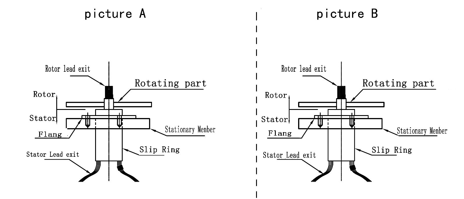
Picture A
1. Position the slip ring in the desired location and tighten both set screws to the shaft . Maximum torque 25Ib-in(DO NOT OVER TOQUE)
2. Route the wiring and make neccessary connections . Do not allow the wiring to restrict free rotation of the slip ring .Do not constrain wiring such that wire flexing occurs . Doing so will ultimately cause failure(breakage of the wiring)
Picture B
1. Align the mouting holes(M3x8) in the flange to mouting base and install mouting screws(M3), securely tighten screws.
2. Route the wiring and make the neccessary connections . Donot allow the wiring to restrict free rotations of the slip ring .
CAUTION:
Because of possible geometric mismatching between the customer's application and the slip ring , 'hard mouting' of both ends of the slip ring(i.e,.securing the rotor and stator such that there is no floating during operation) is not recommended and may cause premature failure.

